

How To Create Exploded View In Solidworks
SolidWorks: Exploded Views
Exploding an assembly view in SolidWorks can make all the difference when trying to show every component involved in the making. Instead of showing multiple views and angles, one view can be used to show all components. A well done exploded view will also help in the understanding of how the entire assembly fits together. Exploded views are used in almost every industry when it comes to explaining a product and how it works. Knowing how to use the exploded view feature is a crucial key feature and will be finishing touch needed when showing an assembly.
Feature/Icon Location
Exploded views are only able to be performed on an assembly, not a single part. Therefore, the exploded view icon is only located inside of an assembly file. To reach the icon it can either be found on the assembly tab toolbar or can be created by going under the configurations tab and right clicking on the assembly icon and creating a new exploded view. Both locations are shown below in Figure 1.

Figure 1: Feature/Icon locations
Exploded View Feature Manager
There are two types of exploded view step types to choose from, as seen in Figure 2. There is a regular step and radial step. By choosing regular step, objects selected, being one or multiple, will all move in the same direction with each other. The radial step type is mostly used on parts that are in a circular type pattern. When using a radial step, all parts chosen will move away from each other from a common center point when dragged. Almost as if they are lying on a circle that's radius is expanding. The focus of this blog will stay on regular step exploding since this is the most common type to be used.
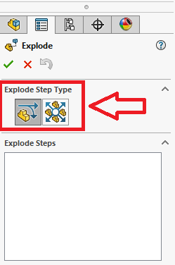
Figure 2: Explode step types
Exploded part selection
Exploding an assembly using regular step type is quite simple. After choosing the step type the components that are desired to be moved are selected and dragged, this can be one part or multiple. If multiple parts are highlighted at the same time they will all move in the same direction when pulled. The direction is chosen by the user. After clicking on a part to be moved an origin point is shown on the selected part showing the possible direction and rotation options. Simply click and hold on the arrow in the direction that is desired and drag the mouse. After the components are moved an "exploded step 1" will appear in the exploded steps view box inside the feature manager. From here previous steps can be edited by right-clicking on them. An example of these steps is shown in Figure 3 below.

Figure 3: Explode step 1
Under the part selection box in the feature manager, there is the option to input set values for how far the part will move and what rotation angle can be put on the selected part. These can be used for exact spacing of exploded parts if it is needed. There is also an explode direction selection box located below the part selection box, as shown in Figure 4. In this selection box, the direction of the exploded step can be changed to match a face or axial direction of another part located inside of the assembly. This can help in the overall flow of the exploded view, giving it a cleanly spaced look when the exploded view is finished.

Figure 4: Set value locations & Explode direction change
Other Exploded Options
Located at the bottom of the exploded view feature manager are a few other options to choose from when exploding an assembly. A very helpful one is the option to turn off and on select subassembly parts. This allows you to move a subassembly as one whole part or one part of the subassembly at a time. This option can only be applied if there is a subassembly inside the assembly that is being exploded. There is also a button that gives the option to reuse a subassembly explosion. If a subassembly being used has already previously been exploded, by clicking this button that exploded state will be shown and it will not have to be redone! These options are shown in Figure 5.

Figure 5: Subassembly explode options
After Exploding The Assembly
Once the assembly has been fully exploded it can be quite hard to tell just exactly where everything has come from and where everything goes back to. Especially in an assembly with a large number of parts. There is an option to add smart explode lines to help with this. These lines, when added in, follow the path that every part was dragged from all the way back to its origin. This helps greatly in showing how an assembly is put together. However, if there are a large number of parts the lines can become cluttered and overwhelming, this option can be left up to personal preference. In Figure 6 below a final exploded assembly is shown with smart lines as well as the location of where to add in the smart lines.
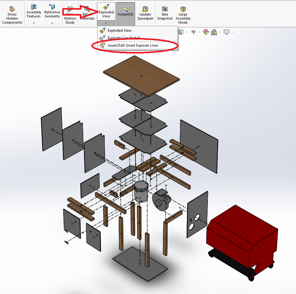
Figure 6: Full exploded view with smart lines
Things to look out for
When exploding an assembly, make sure all components can be seen from one view. Typically for exploded assemblies, the viewpoint is from an isometric view. Also, when exploding an assembly, after clicking off a part, the assembly may collapse and go back to its original state. You do not have to redo the entire exploded assembly. Simply go back to the configurations tab and under the exploded view configuration, right click and hit edit feature, the assembly will re-explode.
If you would like to learn more, check out these course that provide everything you need to know to get started!
Written By:

Hayden Kemme
CAD Designer at Perception Engineering
How To Create Exploded View In Solidworks
Source: https://www.perceptioneng.com/blogold/2018/5/16/solidworks-exploded-views
Posted by: williamsforem1954.blogspot.com
0 Response to "How To Create Exploded View In Solidworks"
Post a Comment